Products
Headquarter
PVTVM Inc
10200 W. Airport Blvd., Suite 170
Stafford TX 77477 USA
Phone: +1-713-830-7601
Phone: +1-281-258-4162
Email: sales@pvtvm.com
.
.
South& North America Areas
Vibravista LLC.
Master Distributor
Phone: +1-713-882-6677
Email: sales@vibravista.com
.
.
Europe, Middle East and Africa Areas
PVTVM- EMEA
Master Distributor
Eislerstrasse 28
91717 Wassertruedingen
Germany
Phone: +49-9832-65889
Fax: +49-9832-65890
Email: emea@pvtvm.com
.
.
China Areas
PVTVM QINGDAO
Room 2208, Huarun Building, N0.6-A Shandong Road,
Shinan District, Qingdao City, China 266000
Phone: +86-532-80771799
Fax: +86-532-86671799
Email: QD@pvtvm.cn
.
.
China Areas
PVTVM BEIJING
Nan Mo Fang Lu 37, Room 1906
Beijing, China 100022
Phone: +86-10-5272-5666
Phone: +86-10-5272-5667
Phone: +86-10-5272-5668
Phone: +86-10-5272-5669
Fax: +86-10-5272-5657
Email: china@pvtvm.cn
.
.
Location:Home>Products>MonitorsMonitors
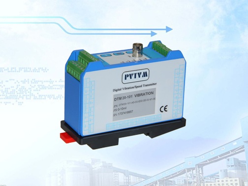
DTM20 Seismic Vibration Distributed Transmitter Monitor

DTM20 monitor can interface with almost any vibration sensor (accelerometer or velocity transducer). The DTM is fully digital and may be configured in the field via DTM-CFG software or come pre-configured from the factory.
Redundant power supplies
Redundant 4-20mA outputs
Dual dry-contact relay outputs
Trip multiply and Bypass
Product Detail
The DTM20 distributed Seismic vibration transmitter-monitor provides a simple and cost-effective solution for monitoring “balance-of-plant” equipment. The DTM’s smart design is extremely reliable with redundancy in power supply inputs, 4-20mA outputs and relay outputs, as well as, a Modbus communication port. The DTM20 monitor can interface with almost any vibration sensor (accelerometer or velocity transducer). The DTM is fully digital and may be configured in the field or come pre-configured from the factory.
Specifications
Electrical
Power:
Redundant. Accept dual power input
20-30VDC @150mA
Isolation: 1000VDC power to signal conditioner circuit
Frequency Response (-3dB):
Nominal Frequency:
2 ~ 3KHz
Low Frequency:
0.5 ~ 100Hz
High Frequency:
10 – 20KHz (peak)
Filters:
Low-pass filter (field programmable):
8-pole (160 dB per decade, 48 dB per octave)
100Hz to 10kHz, field programmed by CFG
High-pass filter (factory setting):
2-pole (40 dB per decade, 12 dB per octave)
4 options (0.5Hz,2Hz,10Hz,100Hz) or custom
Piezo Sensor Interface:
Sensitivity:
100mV/g
100mV/in/sec
4mV/um
or any sensitivity specified
Current Source
Nominal 4mA@24VDC
Seismic Velocity Sensor Interface:
Sensitivity:
User specified for any vibration sensor
Software programmable
Accuracy:
Typical +/-1% FS
Maximum +/-2% FS
Buffered Output:
Original vibration, un-filtered
Impedance: 150Ω
Maximum cable distance: 300m (1000ft)
Sensitivity: same as the sensor
Local BNC connector
On line CM terminals
Overall Vibration output:
Up to two 4-20mA output
4-20mA(1):
Source. Output to controller.
Sharing signal ground
Maximum load resistance 500Ω
4-20mA(2):
Loop. Loop powered by controller.
Galvanic isolation, 1000VDC
Power supply range: 16-30VDC
Maximum load resistance: 50*(Vs-16)
Where Vs is the loop power supply
Alarm Set point:
5 ~ 100% FS
Accuracy:
±0.1%.
Delay: 1~60s, according to 1 second increase, default is 3s.
Relays:
Seal: Epoxy.
Capacity: 0.2A/240VAC,
0.4A/110VAC
2.0A/24VDC, resistive load
Relay type: SPTD
Isolation: 1000VDC
Push Buttons:
SET: System on-site calibration and alarm setting
+ : Adjustment increment
- : Adjustment decrement
LED Machine Condition Indicator:
OK: System OK indication
ALT: Vibration over Alert level
DNG: Vibration over Danger level
BYP: System in BYPASS
TRX: Digital transmission active
RESET/BYPASS
Trip-Multiply
Modbus RTU
Digital Condition Monitoring
Physical
Dimension:
Height: 75mm (2.95″)
see figure below
Weight: 0.9lb (0.4kg)
Environmental
Temperature:
Operation: -40℃ ~ +85℃.
Storage: -50℃ ~ +100℃.
Humidity: 90% non-condensing.
Case: Aluminum cast (copper free)